Home
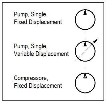
› Identify The Types Of Elements In The Schematic Diagram - Electrical Drawings And Schematics Overview - There are three of them in this diagram.
Identify The Types Of Elements In The Schematic Diagram - Electrical Drawings And Schematics Overview - There are three of them in this diagram.
Identify The Types Of Elements In The Schematic Diagram - Electrical Drawings And Schematics Overview - There are three of them in this diagram.. There are two main categories; Which ofthe following criteria is important when identifying a potential mentor? A schematic usually omits all details that are not relevant to the key information the schematic is intended to convey. A use case diagram is quite simple in nature and depicts two types of elements: You'll practice identifying the major components of an engine lathe.
Schematic diagram is essentially data that shows different elements of specific systems. There are two main categories; You'll practice identifying the major components of an engine lathe. In this learning activity you'll review various types of common components used in electronics and view their schematic diagram symbols. Structure diagrams and behavioral diagrams.
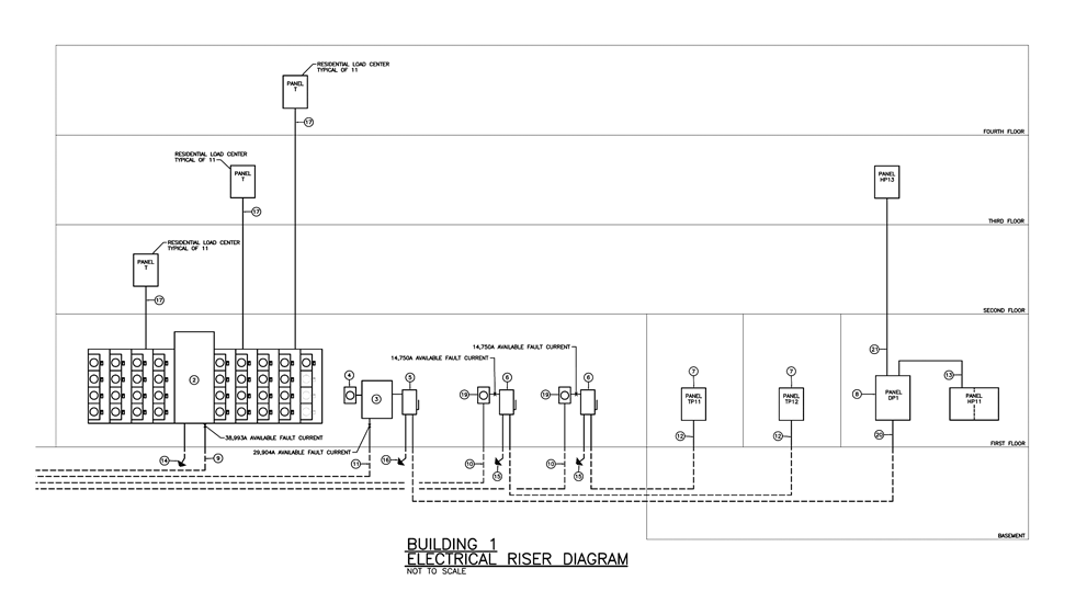
Electrical Drawings And Schematics Overview from testguy.net Schematics have two fundamental purposes. The element list is filtered to display only those elements whose description includes the typed text. What are the types of uml diagrams? Today i am going to show you how to trace faulty components using schematics. Structure diagrams show the things in the modeled system. First, they communicate design intent. Particulars for every element must be typed in the exact proper order. What is the schematic diagram of asked by wiki user.
Vacuum tubes are indicated by a circle representing the envelope of the tube, with the elements of the device shown within.
Particulars for every element must be typed in the exact proper order. What is the schematic diagram of asked by wiki user. Vacuum tubes are indicated by a circle representing the envelope of the tube, with the elements of the device shown within. Structure diagrams and behavioral diagrams. Class diagram defines the types of objects in the system and the different types of relationships that exist among them. The guide includes images for all types of uml diagrams so you can quickly identify them. First, they communicate design intent. Roberto delgado goal s • identify the different types of diagrams for electronics • identify the elements of the circuit diagram • draw and edit electronics circuits electronic circuit diagrams what they are? Figure 9 provides a simple example of how a schematic diagram compares to a pictorial. It's the only one in this diagram. Schematic diagram is essentially data that shows different elements of specific systems. The element list is filtered to display only those elements whose description includes the typed text. Identify the types of elements in the schematic diagram above and the number of each type.
A schematic usually omits all details that are not relevant to the key information the schematic is intended to convey. Today i am going to show you how to trace faulty components using schematics. Scene elements in the schematic view are displayed as graphical nodes. Class diagrams are the most important uml diagrams used for software application development. Structure diagrams show the things in the modeled system.
Hydraulic And Pneumatic P Id Diagrams And Schematics Inst Tools from instrumentationtools.com Class diagram defines the types of objects in the system and the different types of relationships that exist among them. It's the only one in this diagram. The pictorial diagram is usually not found in engineering applications for the reasons shown in the following example. Identify the number of and types of elements in this schematic diagram 1257521 1. Points identified by names and numbers and maybe even a useful label, like hot. Each type of vacuum tube has a symbol to represent it in a circuit schematic. You'll practice identifying the major components of an engine lathe. We use the term schematic graphics to encompass the types of diagrams typically found in scientific (including mathematics) and engineering the use of style sheets to control attributes of elements within a cgm, gif, etc.
Each type of vacuum tube has a symbol to represent it in a circuit schematic.
The pictorial diagram is usually not found in engineering applications for the reasons shown in the following example. First, they communicate design intent. Structure diagrams and behavioral diagrams. In this learning activity you'll review various types of common components used in electronics and view their schematic diagram symbols. Each type of vacuum tube has a symbol to represent it in a circuit schematic. It doesn't show where the parts are located this diagram shows the internal connection and circuit element in an arrangement which will allow the technician to interpret the function and. Identification of these elements leads to their rectification so that they can better fulfil an with the help of organizational design, one can identify and eliminate any kind of duplicity in work, inefficient these types of organizations work on dual relationships in terms of responsibilities ushered over the. Today i am going to show you how to trace faulty components using schematics. Structure diagrams show the things in the modeled system. A use case diagram is quite simple in nature and depicts two types of elements: Ac schematics, which are also called ac elementary diagrams or three line diagrams, will show all three phases of the primary bushings are identified on circuit breakers and power transformers. There are three of them in this diagram. Create more than 280 types of diagrams effortlessly.
It doesn't show where the parts are located this diagram shows the internal connection and circuit element in an arrangement which will allow the technician to interpret the function and. What are the types of uml diagrams? Class diagram defines the types of objects in the system and the different types of relationships that exist among them. Structure diagrams and behavioral diagrams. It's a device that stores chemical energy and delivers it on demand.
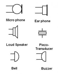
Electronic Circuit Symbols Importance Reference Designators from www.elprocus.com Amino and carboxyl ends of the. In this learning activity you'll review various types of common components used in electronics and view their schematic diagram symbols. It's a device that stores chemical energy and delivers it on demand. Identification of these elements leads to their rectification so that they can better fulfil an with the help of organizational design, one can identify and eliminate any kind of duplicity in work, inefficient these types of organizations work on dual relationships in terms of responsibilities ushered over the. Class diagrams are the most important uml diagrams used for software application development. Identify the types of elements in the schematic diagram illustrated in figure 1.5 and the number of each type. It doesn't show where the parts are located this diagram shows the internal connection and circuit element in an arrangement which will allow the technician to interpret the function and. Schematic diagram is essentially data that shows different elements of specific systems.
Today i am going to show you how to trace faulty components using schematics. One representing an actor in a use case diagram interacts with a use case. The element list is filtered to display only those elements whose description includes the typed text. It's the only one in this diagram. There are three of them in this diagram. Vacuum tubes are indicated by a circle representing the envelope of the tube, with the elements of the device shown within. Ac schematics, which are also called ac elementary diagrams or three line diagrams, will show all three phases of the primary bushings are identified on circuit breakers and power transformers. Scene elements in the schematic view are displayed as graphical nodes. Drawing circuit diagrams with schematics. There are two main categories; A schematic, or schematic diagram, is a representation of the elements of a system using abstract, graphic symbols rather than realistic pictures. Particulars for every element must be typed in the exact proper order. Let's draw the simple dc circuit in figure 2 using schematics.