Home
› Diagram Irfp250 Mosfet Amplifier : 600w Mosfet Power Amplifier Amplifier Circuit Design / This is the circuit design of mosfet power amplifier 5200w rms, the schematic is for single channel.
Diagram Irfp250 Mosfet Amplifier : 600w Mosfet Power Amplifier Amplifier Circuit Design / This is the circuit design of mosfet power amplifier 5200w rms, the schematic is for single channel.
Diagram Irfp250 Mosfet Amplifier : 600w Mosfet Power Amplifier Amplifier Circuit Design / This is the circuit design of mosfet power amplifier 5200w rms, the schematic is for single channel.. To do this, i planned to build an amplifier using a pair of mosfet's as the final amplifier stage. Stmicroelectronics, alldatasheet, datasheet, datasheet search site for electronic components and semiconductors, integrated circuits, diodes, triacs, and other semiconductors. Here is the 200w mosfet amplifier powered based on four piece of irfp250n, they are very cheap and easy to find in the electronic market in your area. Hf amplifiers for ham radio use. Here is the 200w mosfet amplifier powered based on four piece of irfp250n, they are very cheap and easy to find in the electronic market in your area.
The amplifier has a low distortion of 0.1%, a damping factor greater than 200, input sensitivity of 1.2v and the bandwidth is from 4hz to 4 khz. Here is the 200w mosfet amplifier powered based on four piece of irfp250n, they are very cheap and easy to find in the electronic market in your area. This is the first mosfet output power amplifier of 'l' series, 'l 150 w fet amp' The final stage amplifier using 4 x mosfet transistor irfp260 or you can use irfp250 / irfp460 / irfp4227. The circuit has been assembled and tested with very good performance.
Pin On 5200 from i.pinimg.com And do not forget to lose the importance of the lpf filter. Capacitor c8 is the dc input decoupling, c1 r1 limits input current and a capacitor bypasses undesirable high frequencies. The second stage is composed of the pilot phase transistors q3 and q4. This is the circuit design of mosfet power amplifier 5200w rms, the schematic is for single channel. To feed this circuit , you will need 150 volts dual polarity (symmetrical) power supply of course with very high dc current. I knew the starpoint would not directly drive the mosfet's, because it just didn't have the rf power output required to handle the gate charge required by. The circuit has been assembled and tested with very good performance. The circuit has been assembled and tested with very good performance.
Capacitor c8 is the dc input decoupling, c1 r1 limits input current and a capacitor bypasses undesirable high frequencies.
The circuit has been assembled and tested with very good performance. The idea was developed a long time ago by the hitachi researchers and still it remains one of the favorite designs of all time considering the. Here is the 200w mosfet amplifier powered based on four piece of irfp250n, they are very cheap and easy to find in the electronic market in your area. Nowadays it is used as a power subwoofer amplifier driver board. Capacitor c8 is the dc input decoupling, c1 r1 limits input current and a capacitor bypasses undesirable high frequencies. The final stage amplifier using 4 x mosfet transistor irfp260 or you can use irfp250 / irfp460 / irfp4227. Irfp250, sihfp250vishay siliconixpower mosfetfeaturesproduct summary dynamic dv/dt ratingvds (v) 200 repetitive avalanche rated availablerds(on) ()vgs = 10 v 0.085 isolated central mounting holerohs*qg (max.) (nc) 140compliant fast switchingqgs (nc) 28 ease of parallelingqgd (nc) 74 simple drive requirementsconfiguration single compli. The circuit has been assembled and tested with very good performance. The first stage of the 50 watt mosfet amplifier is a differential amplifier based on transistors q1 and q2. 600w high power 2 provided with circuit bridge connection (4 ohm speakers with 1000w) for a total of 4 pcs fdp2532 mosfet is used (instead of irfp250) mosfet driver circuits is controlled with the ir2110 mosfets.class d amplifier circuit used coils 30uh worth ei33 core wrap tie wire 0. Pa amplifier acss push pull transformer driver coil and 100 to 5000 watt pa amplifier available This is the first mosfet output power amplifier of 'l' series, 'l 150 w fet amp' 200w mosfet amplifier based irfp250n | electronic schematic diagram 200w mosfet amplifier based irfp250n here is the 200w mosfet amplifier powered based on four piece of irfp250n, they are very cheap and easy to find in the electronic market in your area.
I had already used mosfet's in my 400 watt output qrss30 / cw transmitter with good results. 100w mosfet power amplifier circuit Nowadays it is used as a power subwoofer amplifier driver board. Category is a curation of 95 web resources on , 40m linear amlifier made by 9a6a, 4 kw rf amplifier, adding 160m to hf amplifiers. The second stage is composed of the pilot phase transistors q3 and q4.
Vasp 100 Watt Mosfet Assembled Amplifier Board Using Irfp240 Irfp9240 Power Mosfet For Home Audio Diy Projects 1 Piece Amazon In Industrial Scientific from images-na.ssl-images-amazon.com Class d amplifier circuits switch mode switched work thanks so much less material with higher power can give. The idea was developed a long time ago by the hitachi researchers and still it remains one of the favorite designs of all time considering the. An advantage of mosfet devices is that they do not have gate leakage current and mosfets do not need input and reverse transconductance. Stmicroelectronics, alldatasheet, datasheet, datasheet search site for electronic components and semiconductors, integrated circuits, diodes, triacs, and other semiconductors. And do not forget to lose the importance of the lpf filter. With a power supply of ± 30v the mosfet audio amplifier can deliver 45w on 8 ω and 70w on 4ω. The advantages of this high power amplifier are: I knew the starpoint would not directly drive the mosfet's, because it just didn't have the rf power output required to handle the gate charge required by.
The amplifier has a low distortion of 0.1%, a damping factor greater than 200, input sensitivity of 1.2v and the bandwidth is from 4hz to 4 khz.
Nowadays it is used as a power subwoofer amplifier driver board. The circuit has been assembled and tested with very good performance. The second stage is composed of the pilot phase transistors q3 and q4. See the circuit schematic diagram and pcb layout design here,. 600w high power 2 provided with circuit bridge connection (4 ohm speakers with 1000w) for a total of 4 pcs fdp2532 mosfet is used (instead of irfp250) mosfet driver circuits is controlled with the ir2110 mosfets.class d amplifier circuit used coils 30uh worth ei33 core wrap tie wire 0. Pa amplifier acss push pull transformer driver coil and 100 to 5000 watt pa amplifier available The simple mosfet amplifier circuit diagram is super simple to build and yet will provide you with a crystal clear 100 watts of raw music power that all the listeners will cherish for a long time. The second stage is composed of the pilot phase transistors q3 and q4. The amplifier can be also used as a sub woofer amplifier but a subwoofer filter stage has to be added before the input stage. Capacitor c8 is the dc input decoupling, c1 r1 limits input current and a capacitor bypasses undesirable high frequencies. This is the circuit design of mosfet power amplifier 5200w rms, the schematic is for single channel. Stmicroelectronics, alldatasheet, datasheet, datasheet search site for electronic components and semiconductors, integrated circuits, diodes, triacs, and other semiconductors. This 200w mosfet amplifier circuit designed for single or mono audio channel application.
The final stage amplifier using 4 x mosfet transistor irfp260 or you can use irfp250 / irfp460 / irfp4227. An advantage of mosfet devices is that they do not have gate leakage current and mosfets do not need input and reverse transconductance. To do this, i planned to build an amplifier using a pair of mosfet's as the final amplifier stage. This is the circuit design of mosfet power amplifier 5200w rms, the schematic is for single channel. The idea was developed a long time ago by the hitachi researchers and still it remains one of the favorite designs of all time considering the.
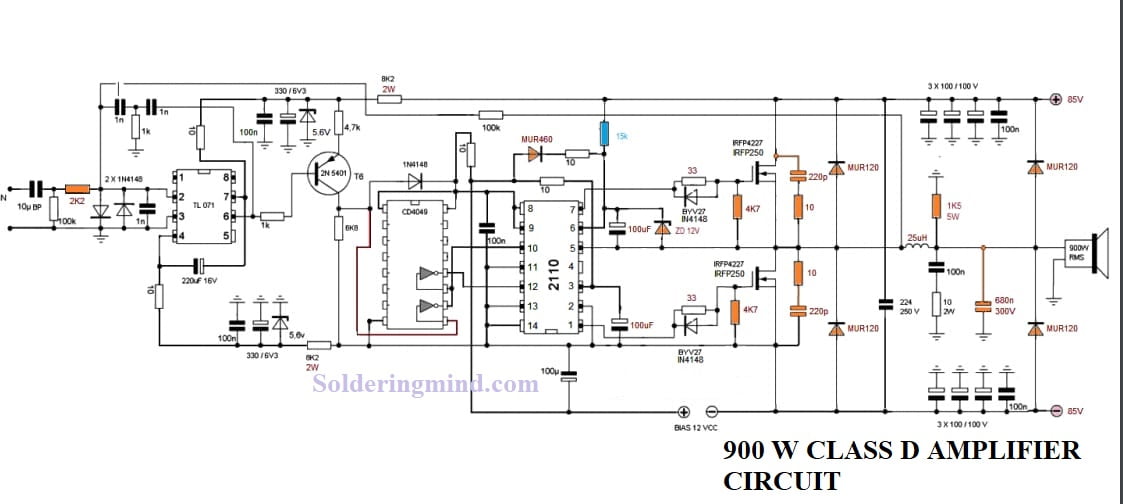
900w Class D Next Generation Power Amplifier Class D Amplifier Circuit from solderingmind.com Here is the 200w mosfet amplifier powered based on four piece of irfp250n, they are very cheap and easy to find in the electronic market in your area. The second stage is composed of the pilot phase transistors q3 and q4. Capacitor c8 is the dc input decoupling, c1 r1 limits input current and a capacitor bypasses undesirable high frequencies. I had already used mosfet's in my 400 watt output qrss30 / cw transmitter with good results. High power 600 watt quasi amplifier mosfet irfp460. The simple mosfet amplifier circuit diagram is super simple to build and yet will provide you with a crystal clear 100 watts of raw music power that all the listeners will cherish for a long time. The circuit has been assembled and tested with very good performance. Irfp250, sihfp250vishay siliconixpower mosfetfeaturesproduct summary dynamic dv/dt ratingvds (v) 200 repetitive avalanche rated availablerds(on) ()vgs = 10 v 0.085 isolated central mounting holerohs*qg (max.) (nc) 140compliant fast switchingqgs (nc) 28 ease of parallelingqgd (nc) 74 simple drive requirementsconfiguration single compli.
Nowadays it is used as a power subwoofer amplifier driver board.
And do not forget to lose the importance of the lpf filter. See more ideas about circuit diagram, subwoofer, circuit. Nowadays it is used as a power subwoofer amplifier driver board. The circuit uses 16x irfp250 to gain 5200w rms power output at 2 ohms load. The second stage is composed of the pilot phase transistors q3 and q4. Class d amplifier circuits switch mode switched work thanks so much less material with higher power can give. This 200w mosfet amplifier circuit designed for single or mono audio channel application. The circuit has been assembled and tested with very good performance. The simple mosfet amplifier circuit diagram is super simple to build and yet will provide you with a crystal clear 100 watts of raw music power that all the listeners will cherish for a long time. Stmicroelectronics, alldatasheet, datasheet, datasheet search site for electronic components and semiconductors, integrated circuits, diodes, triacs, and other semiconductors. Hf amplifiers for ham radio use. An advantage of mosfet devices is that they do not have gate leakage current and mosfets do not need input and reverse transconductance. This 200w mosfet amplifier circuit designed for single or mono audio channel application.