Wiring Pin Diagram : Wiring Diagram For 4 Pin Trailer Plug | Trailer Wiring Diagram / Electrical schematic & wiring diagrams.. Fitting instructions for all 13 pin kits and relays. It shows the components of the circuit as simplified shapes, and the power and signal connections between the devices. Type of wiring diagram wiring diagram vs schematic diagram how to read a wiring diagram: Jump to navigation jump to search. Positive connection (left turn signal bulb), in main wiring harness.
Beware that there is more than one colour scheme but pins 1 to 7 inclusive are colour coded the same in each. He also explains why this proper firing. Understanding relays & wiring diagrams what's the difference between 4 and 5 pin relays? A wiring diagram is a simplified conventional pictorial representation of an electrical circuit. Normally open or normally closed.
Wiring Diagram for 7-Way Round Pin Trailer and Vehicle Side Connectors | etrailer.com from www.etrailer.com The following shows how to replace the firing pin, extractor, and rollers with harrington products upgrades. The dys comes with its own cables which are also sh type but will need to be snipped and soldered using the pin diagrams. Briggs & stratton supplies electrical components pertaining to the engine only. This wiring method is fully compatible with any 4 pin denso relay starting with the serial number 156700 or look like the sample denso relays below. Positive connection (left turn signal bulb), in main wiring harness. Understanding relays & wiring diagrams what's the difference between 4 and 5 pin relays? From wikimedia commons, the free media repository. With such an illustrative guide, you'll be capable of troubleshoot, stop, and complete your tasks easily.
A wiring diagram is a simplified conventional pictorial representation of an electrical circuit.
This pictorial diagram shows us the. Electrical schematic & wiring diagrams. Type of wiring diagram wiring diagram vs schematic diagram how to read a wiring diagram: Load cell connector wiring diagram. It shows how the electrical wires are interconnected and can also show where fixtures and components may be connected to the system. Print or download electrical wiring & diagrams. The usb cable has typically four wires to connect the a type connector. Wiring & pin out diagrams. Normally open or normally closed. Understanding relays & wiring diagrams what's the difference between 4 and 5 pin relays? What is the firing order before tdc. I have found images for the colt series 80 and the kimber series ii, but i. The dys comes with its own cables which are also sh type but will need to be snipped and soldered using the pin diagrams.
The gps module can directly be connected without any modification. I have found images for the colt series 80 and the kimber series ii, but i. The wiring diagram is given below to help you wire it properly. Lihat ide lainnya tentang rangkaian elektronik, diagram, teknik komputer. The usb cable has typically four wires to connect the a type connector.
Airstream 7 Pin Wiring Diagram - Wiring Forums from i2.wp.com This pictorial diagram shows us the. Understanding relays & wiring diagrams what's the difference between 4 and 5 pin relays? I have found images for the colt series 80 and the kimber series ii, but i. The wiring diagram includes any combination of different types of usb connectors. With such an illustrative guide, you'll be capable of troubleshoot, stop, and complete your tasks easily. Anyone have a diagram or actual picture of the sw1911 firing pin safety system? This wiring method is fully compatible with any 4 pin denso relay starting with the serial number 156700 or look like the sample denso relays below. .pin wiring diagram wiring diagram repair guide just push the gallery or if you are interested in similar gallery of miller 14 pin connector wiring diagram wiring diagram repair guide can be a beneficial inspiration for those who seek an image according to specific categories like wiring.
Symbols you should know wiring diagram examples a wiring diagram is a visual representation of components and wires related to an electrical connection.
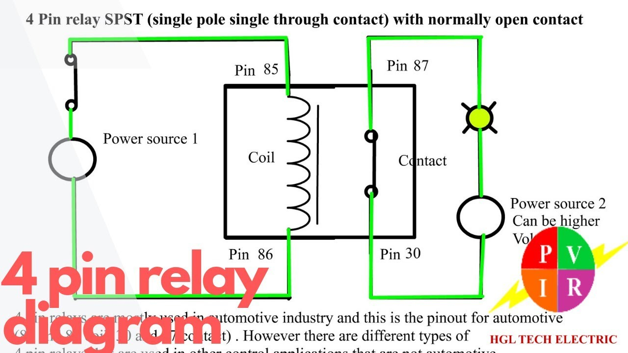
Beware that there is more than one colour scheme but pins 1 to 7 inclusive are colour coded the same in each. Relay schematics and diagrams there are 2 types of 4 pin relay available; The daq board supports input voltages from 5 v to 50 v, and output voltages from 5 v to 40 v. Lihat ide lainnya tentang rangkaian elektronik, diagram, teknik komputer. Normally open or normally closed. It shows how the electrical wires are interconnected and can also show where fixtures and components may be connected to the system. He also explains why this proper firing. This wiring method is fully compatible with any 4 pin denso relay starting with the serial number 156700 or look like the sample denso relays below. If you are only upgrading some of your parts, use the appropriate steps of the following. Need a diagram and markings to set the crankshaft & twin overhead camshaft timing; If you are not sure how to properly wire the device, consult the advantech manual. What is the firing order before tdc. It shows the components of the circuit as simplified shapes, and the power and signal connections between the devices.
If you are not sure how to properly wire the device, consult the advantech manual. Beware that there is more than one colour scheme but pins 1 to 7 inclusive are colour coded the same in each. The gps module can directly be connected without any modification. The wiring diagram is given below to help you wire it properly. With such an illustrative guide, you'll be capable of troubleshoot, stop, and complete your tasks easily.
4 Prong Relay Wiring Diagram | Wiring Diagram from 2020cadillac.com In part 2 of the wiring diagram series we answer a few questions that we had from part one, talk wire colors and pin locations, and get into a diagram that. Electrical schematic & wiring diagrams. The following shows how to replace the firing pin, extractor, and rollers with harrington products upgrades. I have found images for the colt series 80 and the kimber series ii, but i. 3 pin fan connections *cable coloring varies from fan to fan. The wiring diagram is given below to help you wire it properly. Lihat ide lainnya tentang rangkaian elektronik, diagram, teknik komputer. In europe both 7 pin iso 1724 and 13 pin iso 11446 are common.
Normally open or normally closed.
This pictorial diagram shows us the. With such an illustrative guide, you'll be capable of troubleshoot, stop, and complete your tasks easily. 3 pin fan connections *cable coloring varies from fan to fan. Type of wiring diagram wiring diagram vs schematic diagram how to read a wiring diagram: The daq board supports input voltages from 5 v to 50 v, and output voltages from 5 v to 40 v. Wiring diagram a wiring diagram shows, as closely as possible, the actual location of all component parts of the device. Electrical schematic & wiring diagrams. A wiring diagram is a simplified conventional pictorial representation of an electrical circuit. Wiring & pin out diagrams. Load cell connector wiring diagram. However, basic schematics of our alternator systems wired to a generic piece of equipment are available in our Wiring diagram for a 13pin euro trailer plug. If you are not sure how to properly wire the device, consult the advantech manual.