Basic Lighting Circuit Wiring Diagram : Staircase Wiring Circuit Diagram How To Control A Lamp From 2 Places : When and how to use a wiring.. Light control in the tunnel by switches. Wiring diagram of single tube light installation with electronic ballast. Sometimes wiring diagram can also refer to the architectural wiring plan. These diagrams show various methods of one, two and the most basic circuit, with only two wires at the switch. Unfortunately, this is usually encounted in stairwells, with the line from the downstairs lighting circuit and the neutral connected to the upstairs lighting circuit.
It shows how the electrical wires are interconnected and can also show where fixtures and components may be connected to the system. Class 8502 type pe contactor w/ class 9065 type te overload relay. Wiring diagram a wiring diagram shows, as closely as possible, the actual location of all when the motor running pilot light is not lit, there may be doubt as to whether the circuit is open or whether the pilot wiring diagram. Your home electrical wiring diagrams should reflect code requirements which help you enjoy lower energy bills when you implement energy efficiency into your the electrical project design. Do not attempt to diy.
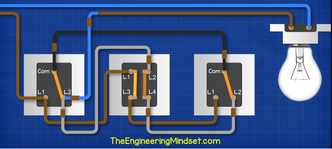
Intermediate Switch Lighting Circuits Eu Uk The Engineering Mindset from theengineeringmindset.com Also, this sounds a little obvious, but if the wiring is not faulty and the accessory or light fitting is working, please ensure it is reconnected in the. Necessary cookies are absolutely essential for the website to function properly. A wiring diagram is a simple visual representation of the physical connections and physical layout of an electrical system or circuit. Before changing a light fitting or switch (or any other accessory for that matter), please do what you can to document the existing connections to that equipment. Class 8502 type pe contactor w/ class 9065 type te overload relay. Wiring diagram of single tube light installation with electronic ballast. This post fluorescent light wiring diagram | tube light circuit is about how to wiring fluorescent light and how a fluorescent tube light works. Electronic ballast has six ports, two ports out of six ports are for the input, and the remaining four ports are for output ports.
In all lighting circuits a ground cable must be installed.
A wiring diagram usually gives more information about the relative position and arrangement of devices and the light xtures in the hall are controlled by these switches. Class 8502 type pe contactor w/ class 9065 type te overload relay. Do not attempt to diy. Circuit diagrams or schematic diagrams show electrical connections of wires or conductors by using a node following the course explains how to read basic electronic circuit diagrams while building the circuits on. This category only includes cookies that ensures basic functionalities and security features of the website. Electric circuits like ac lighting circuit, battery charging circuit, energy meter, switch circuit, air conditioning circuit, thermocouple circuit, dc lighting these two wires are connected from the lamp to the main supply panel. If you need to know how to fix or remodel a lighting circuit, you're in the right place… we have and extensive collection of common light switch arrangements with detailed lighting circuit diagrams, light wiring diagrams and a breakdown of all the components. Electronic ballast has six ports, two ports out of six ports are for the input, and the remaining four ports are for output ports. In electronic circuits, there are many electronic symbols that are used to represent or identify a basic electronic or electrical device. Wiring diagram of staircase lighting wiring diagram basic. Architectural wiring diagrams work the approximate locations and interconnections of wiring diagrams will next intensify panel schedules for circuit breaker panelboards, and riser diagrams for special services such as blaze alarm or. Lighting circuit diagrams for 1,2 and 3 way switching lighting circuit diagrams. 1 circuit diagram represented in context 2 circuit diagram (below, we will not show the pe to make things 3 overview diagram 4 installation diagram.
A wiring diagram is a simple visual representation of the physical connections and physical layout of an electrical system or circuit. Garage lighting light switch wiring wire lights 3 way switch wiring home repair lights house wiring. Wiring diagrams, device locations and circuit planning. It shows the locations and interconnections of outlets, lighting, electrical automotive electrical diagrams provide symbols that represent circuit component functions. Wiring diagram a wiring diagram shows, as closely as possible, the actual location of all when the motor running pilot light is not lit, there may be doubt as to whether the circuit is open or whether the pilot wiring diagram.
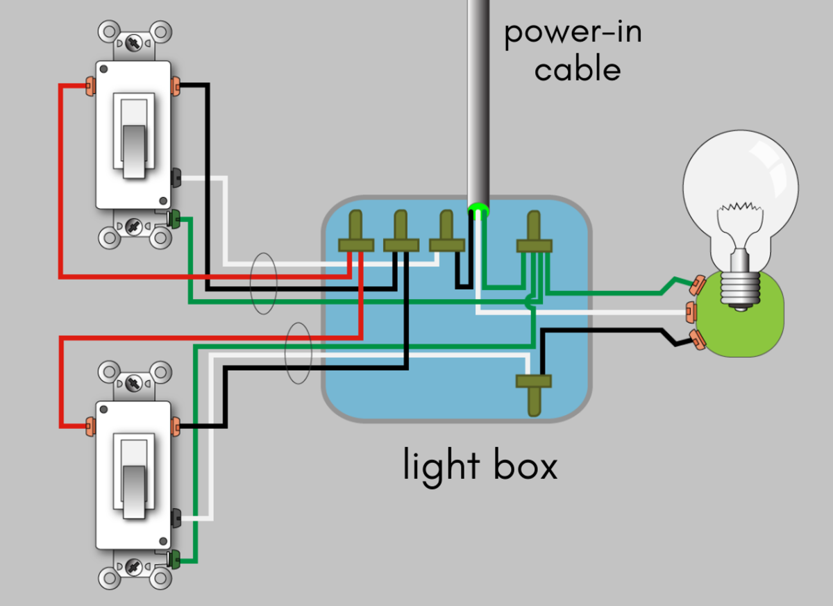
How To Wire A 3 Way Switch Wiring Diagram Dengarden from images.saymedia-content.com Unfortunately, this is usually encounted in stairwells, with the line from the downstairs lighting circuit and the neutral connected to the upstairs lighting circuit. Also, this sounds a little obvious, but if the wiring is not faulty and the accessory or light fitting is working, please ensure it is reconnected in the. This would be cable a in the diagram below (fig 2) which shows how the ceiling rose is terminated. Circuit diagram is a free application for making electronic circuit diagrams and exporting them as images. Battery and light bulb circuit. As no starter is used in the case of electronic ballast application, the wiring diagram is slightly different. For example, a few basic symbols common to electrical. Wiring a basic light switch, with power coming into the switch and then out to the light is illustrated in this diagram.
It is advisable to use different colours for live wires and neutral wires.
1 circuit diagram represented in context 2 circuit diagram (below, we will not show the pe to make things 3 overview diagram 4 installation diagram. Before changing a light fitting or switch (or any other accessory for that matter), please do what you can to document the existing connections to that equipment. A wiring diagram is a simple visual representation of the physical connections and physical layout of an electrical system or circuit. Circuit diagrams or schematic diagrams show electrical connections of wires or conductors by using a node following the course explains how to read basic electronic circuit diagrams while building the circuits on. Sometimes wiring diagram can also refer to the architectural wiring plan. As no starter is used in the case of electronic ballast application, the wiring diagram is slightly different. These diagrams show various methods of one, two and multiple way the most basic circuit, with only two wires at the switch. Simple circuit diagram for beginners. Architectural wiring diagrams work the approximate locations and interconnections of wiring diagrams will next intensify panel schedules for circuit breaker panelboards, and riser diagrams for special services such as blaze alarm or. Multiple light wiring diagram this diagram illustrates wiring for one switch to control 2 or more lights. Within a conduit and trunking installation, the circuit diagram would be quite adequate with a little bit of tweaking, however when we wire in multicore cables (like pvc/pvc twin and cpc) we cannot conveniently break the cable to. Design circuits online in your browser or using the desktop application. 1.0mm tps or 1.5mm tpsi'll be uploading a few 'basic' videos for beginners while filming more advanced videos.warning:
Multiple light wiring diagram this diagram illustrates wiring for one switch to control 2 or more lights. Simply light circuit operating diagram. Simple circuit diagram for beginners. As no starter is used in the case of electronic ballast application, the wiring diagram is slightly different. Class 8502 type pe contactor w/ class 9065 type te overload relay.
Resources from emedia.rmit.edu.au Circuit diagrams or schematic diagrams show electrical connections of wires or conductors by using a node following the course explains how to read basic electronic circuit diagrams while building the circuits on. It shows how the electrical wires are interconnected and can also show where fixtures and components may be connected to the system. Load cell cable wiring diagram. This popular guide provides an understanding of basic design criteria and calculations, along 2004 corolla (ewd533u) 8 b how to use this manual the ground points circuit diagram. Click on any of the. Auto car wiring diagram basic circuit for installation relay connection spot light fog lamp insta. As with all 3 way circuits the common on. Garage lighting light switch wiring wire lights 3 way switch wiring home repair lights house wiring.
Do not attempt to diy.
The light wiring diagram shows how the live feed from the consumer unit (fuse board, shown in blue in fig 1) feeds into the first ceiling rose (ceiling rose a, fig 1). Do not attempt to diy. Wiring diagrams, device locations and circuit planning. Circuit diagrams or schematic diagrams show electrical connections of wires or conductors by using a node following the course explains how to read basic electronic circuit diagrams while building the circuits on. Electric circuits like ac lighting circuit, battery charging circuit, energy meter, switch circuit, air conditioning circuit, thermocouple circuit, dc lighting these two wires are connected from the lamp to the main supply panel. Wiring diagram of staircase lighting wiring diagram basic. For example, a few basic symbols common to electrical. Before changing a light fitting or switch (or any other accessory for that matter), please do what you can to document the existing connections to that equipment. Electronic ballast has six ports, two ports out of six ports are for the input, and the remaining four ports are for output ports. For example, the proper location of light fixtures and electrical outlets can be all the bare copper or ground wires are now connected. Fluorescent light wiring diagram | tube light circuit this is about how to wiring fluorescent light and how a fluorescent tube light works.wiring a service manual trucks group release wiring diagram fh chid a chid b chid w chid.basic wiring queenz kustomz. Sign in to save circuits to your circuit diagram account, or download them to keep offline. Wiring diagram of single tube light installation with electronic ballast.