Home
› Heating Wiring Diagram - Integration Kit 240v Relay With Built In Transformer 240v Integration Kit 240v / Hot water heating system zone valve installation:
Heating Wiring Diagram - Integration Kit 240v Relay With Built In Transformer 240v Integration Kit 240v / Hot water heating system zone valve installation:
Heating Wiring Diagram - Integration Kit 240v Relay With Built In Transformer 240v Integration Kit 240v / Hot water heating system zone valve installation:. This wire may be red without an h attached to it, depending on if you have a dual transformer setup. Activate a gas valve from a zone controller; I explain what each of the letter t. As long as the water heater is sized appropriately And you should select the most appropriate diagram that matches the components you have installed in your system along with what you're hoping to achieve in terms of controllability.
Hot water heating system zone valve installation: However your connections may seem a little different on the thermostat itself. Click the icon or the document title to download the pdf. Control wiring for combination boilers thermostats for combination boilers external programmers for combination boilers combination boiler with 2 heating zones, 230v switching combination boiler with 2 heating zones, volt. Wiring diagrams contains all the essential wiring diagrams across our range of heating controls.
Wiring Residential Gas Heating Units from www.achrnews.com This is the heat element. Activate a gas valve from a zone controller; Electric floor heating is an affordable luxury that is now gaining popularity among homeowners. You should place it under the carbon tape. Electric baseboard heat wiring & location specifications: However your connections may seem a little different on the thermostat itself. The rh wire connects to the rh terminal on your thermostat. This diagram illustrates how simple the heating system connected to a combi.
Other wires are shown in pale grey.
Wiring diagrams contains all the essential wiring diagrams across our range of heating controls. Leave extra wire at the control switch/thermostat box for making connections. Wiring diagrams and other information for central heating control systems. The incoming circuit power will be the same as the line, and the cable wiring is connected as the load. • common or c wires are generally blue. The electrical circuit is installed to the location of the thermostat, and the cables of the floor heat mat are brought to this same junction box. And you should select the most appropriate diagram that matches the components you have installed in your system along with what you're hoping to achieve in terms of controllability. The rh wire connects to the rh terminal on your thermostat. Showing flow from boiler, to y plan, or mid position diverter valve, and then onto heating or hot water circuit. See page 8 of this handbook, tcna ej171, and ttmac 301 mj. The rh wire connects to your heating system as opposed to your cooling system. • if there's an orange wire in the connector labeled both w and o/b, then you likely have a heat pump. However your connections may seem a little different on the thermostat itself.
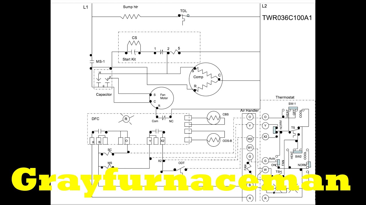
Route quiet warmth lead wires up through the electrical conduit and into the 4 square thermostat box. Thermostats are different temperature and you can always select the desired temp. Here we explain wiring sizes, ratings, fusing, and overcurrent protection for electric heaters and electric baseboards, followed by notes on the proper location for electric heating baseboards to avoid overheating or fires. The incoming circuit power will be the same as the line, and the cable wiring is connected as the load. This diagram shows the wiring layout using the most typical components.
Great Gibson Heat Pump Thermostat Wiring Diagram Nordyne Heat Pump from i.pinimg.com Activate a gas valve from a zone controller; Click the icon or the document title to download the pdf. • if there's a white wire in the connector labeled both w and o/b, It will automatically switch off the heating as soon as the temperature reaches the limit. Other wires are shown in pale grey. The electrical circuit is installed to the location of the thermostat, and the cables of the floor heat mat are brought to this same junction box. Heater, to provide both floor heating and domestic hot water. • if there's an orange wire in the connector labeled both w and o/b, then you likely have a heat pump.
Ensure you have about 1 inch loose at each end of the coil.
What is a wiring diagram? Wiring tips wire colors can vary, but: Wiring diagrams and other information for central heating control systems. As long as the water heater is sized appropriately This diagram shows the wiring layout using the most typical components. Including floor heating in bathroom kitchen or family room. This diagram illustrates how simple the heating system connected to a combi. This article describes how to wire up heating zone valves. Heater, to provide both floor heating and domestic hot water. See page 8 of this handbook, tcna ej171, and ttmac 301 mj. In this figure wiring diagram with thermostat and led. Basics 8 aov elementary block diagram. Control wiring for combination boilers thermostats for combination boilers external programmers for combination boilers combination boiler with 2 heating zones, 230v switching combination boiler with 2 heating zones, volt.
The three additional coloured valve wires are also shown (white, grey and orange). In this hvac installation training video, i show how to wire the low voltage thermostat wires into a furnace and ac unit. Click the icon or the document title to download the pdf. Steps for wiring an electric floor heating system Other wires are shown in pale grey.
The Heat Pump Wiring Diagram Overview Youtube from i.ytimg.com Ensure you have about 1 inch loose at each end of the coil. What is a wiring diagram? Put this wire in the nest thermostat's * o/b connector. Depending on the amperage requirements of multiple thermotile heating mats, a contactor / relay may be required. This is the heat element. Control wiring for combination boilers thermostats for combination boilers external programmers for combination boilers combination boiler with 2 heating zones, 230v switching combination boiler with 2 heating zones, volt. Specific instructions will come with the thermostat for the floor heat system that is chosen. The two systems are basically tied together.
It will automatically switch off the heating as soon as the temperature reaches the limit.
Always follow manufacturers instructions for both the thermostat and the hvac system. Heater, to provide both floor heating and domestic hot water. The incoming circuit power will be the same as the line, and the cable wiring is connected as the load. This diagram shows the wiring layout using the most typical components. Steps for wiring an electric floor heating system 3.1 and 3.2) at the end of these installation guidelines. The same water that ends up in your hot shower or dishwasher, for example, has passed through the floor first. In this figure wiring diagram with thermostat and led. Basics 8 aov elementary block diagram. Wiring the heat exchanger/primary loop system; It will automatically switch off the heating as soon as the temperature reaches the limit. Showing flow from boiler, to y plan, or mid position diverter valve, and then onto heating or hot water circuit. Other wires are shown in pale grey.