Home
› Pressure Transducer Wiring Diagram / Pressure Transducer For Air Water Oil Output 4 20ma 0 10v Rs485 Ato Com / Assortment of pressure transducer wiring diagram.
Pressure Transducer Wiring Diagram / Pressure Transducer For Air Water Oil Output 4 20ma 0 10v Rs485 Ato Com / Assortment of pressure transducer wiring diagram.
Pressure Transducer Wiring Diagram / Pressure Transducer For Air Water Oil Output 4 20ma 0 10v Rs485 Ato Com / Assortment of pressure transducer wiring diagram.. 2005 subaru legacy radio wiring diagram. A wiring diagram is an easy visual representation from the physical connections and physical layout of the electrical system or circuit. A wiring diagram usually gives details regarding the loved one position and also setup of devices and also terminals on the gadgets, in order to help in building or servicing the device. This differs a schematic layout, where the arrangement of the parts' affiliations on the layout usually does not represent the. Assortment of pressure transducer wiring diagram.
4 wire pressure transducer wiring diagramtemperature of a 4 wire transmitter diagram. Pressure transducer wiring diagram source: All circuits usually are the same : So a shorted sensor will render the crank sensor inoperable. You can use this process to set up a system that will log, record, and graph the pressure.
Obsole Te Km10 Pressure Transducer Instruction Sheet Wiring Diagram For All Km10 Transducers Ashcroft Km10 Compact Pressure Transducer User Manual Page 2 2 Original Mode from www.manualsdir.com A wiring diagram typically gives info concerning the relative setting and also plan of tools and also terminals on the gadgets, to assist in structure or servicing the tool. By wiringforumson september 14, 2017 2562 views. Pressure transducers that output milliamp signals can this diagram illustrates the correct wiring. 4 20ma pressure transducer wiring diagram elegant viatran model. A wiring diagram is an easy visual representation from the physical connections and physical layout of the electrical system or circuit. For each type of electrical output, the following wiring instructions and suitable applications are discussed. Get diagram for diagram word diagrams for kids diagram io diagram cirkel diagram online diagram grafiek diagram of ear diagram vertaling diagram of human body organs diagram of the heart. Pressure transducer wiring diagram oil pressure sensor wiring diagram.
Wiring one transducer to multiple readouts, recorders, computers, etc.
Red white black bare red black bare. Duct pressure pressure transducer positive to hi negative to lo double check that the pneumatic tubing is correctly plumbed, firmly seated, and has a tight fit. The net result of the combination of transducer and the figure circuitry is a signal conditioned precision popular posts. Trying to find information regarding pressure transducer wiring diagram? Read electrical wiring diagrams from unfavorable to positive plus redraw the signal being a straight range. 3 wire pressure transducer wiring diagram inspirational four way. Click on the image to enlarge, and then save it to your computer by right clicking on the image. Pressure transducer wiring diagram source: A transducer is an electrical device used to change one form of energy signal to another form of energy signal. Wiring one transducer to multiple readouts, recorders, computers, etc. Connection and programming of sku237545 pressure sensor duration. 5) refer to the wiring diagram for proper transducer wiring (figure 3). Topics wiring diagram symbols electrical wiring diagram toyota wiring.
Effectively read a wiring diagram, one provides to find out how the components within the method operate. B c red black white 1 3 4 red black white black white output series 300 blue red 2 wire wiring diagram example series 300 series 612 & 613 power supply black. 1 3 2 4 1 4 3 * see product congurator for additional options. Polaris sportsman 500 ho problems. Pressure transducer wiring diagram source:
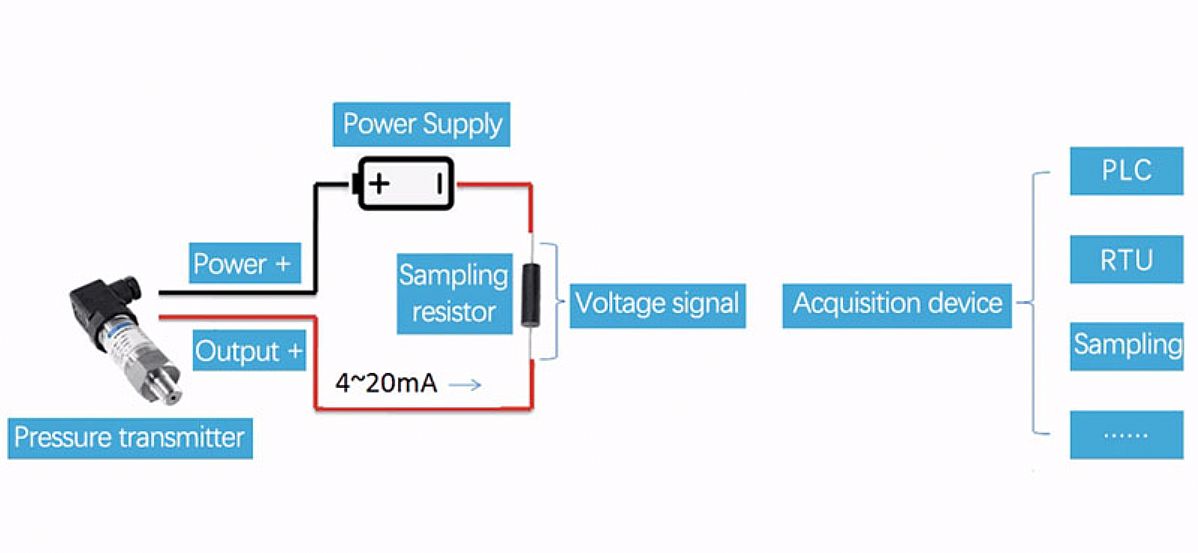
4 20ma Pressure Transmitter Wiring from www.microsensorcorp.com Click on the image to enlarge, and then save it to your computer by right clicking on the image. Assortment of 3 wire pressure transducer wiring diagram. Duct pressure pressure transducer positive to hi negative to lo double check that the pneumatic tubing is correctly plumbed, firmly seated, and has a tight fit. This thesis studies the behavior of the simultaneous flow of oil and water in inclined pipes using a dedicated test loop. April 29, 2019april 29, 2019. Polaris sportsman 500 ho problems. By wiringforumson september 14, 2017 2562 views. 2 wire 4 20 ma sensor transmitters background and compliance rh e2e ti com how a temperature transmitter works learning instrumentation and rh instrumentationtoolbox com what is the difference.
These diagrams depict typical installations.
Pressure transducer wiring diagram oil pressure sensor wiring diagram. Polaris sportsman 500 ho problems. April 29, 2019april 29, 2019. Pressure transducer working and its applications. 4 wire pressure transducer wiring diagramtemperature of a 4 wire transmitter diagram. A wiring diagram usually gives details regarding the loved one position and also setup of devices and also terminals on the gadgets, in order to help in building or servicing the device. This differs a schematic layout, where the arrangement of the parts' affiliations on the layout usually does not represent the. These diagrams depict typical installations. Wiring one transducer to multiple readouts, recorders, computers, etc. For each type of electrical output, the following wiring instructions and suitable applications are discussed. Duct pressure pressure transducer positive to hi negative to lo double check that the pneumatic tubing is correctly plumbed, firmly seated, and has a tight fit. 4 20ma pressure transducer wiring diagram elegant viatran model. Refer to your power supply and instrumentation manufacturer for the specifics of your application.
Assortment of 3 wire pressure transducer wiring diagram. Kpsi™ level and pressure transducers user's manual. Get diagram for diagram word diagrams for kids diagram io diagram cirkel diagram online diagram grafiek diagram of ear diagram vertaling diagram of human body organs diagram of the heart. 4 wire pressure transducer wiring diagram. By wiringforumson september 14, 2017 2562 views.
Ni9219 Ni9221 With 0 5vdc Pressure Transducer Connection Help Ni Community from forums.ni.com Red white black bare red black bare. Read electrical wiring diagrams from unfavorable to positive plus redraw the signal being a straight range. 3 wire pressure transducer wiring diagram inspirational four way. 2005 subaru legacy radio wiring diagram. 1 3 2 4 1 4 3 * see product congurator for additional options. For each type of electrical output, the following wiring instructions and suitable applications are discussed. 4 20ma pressure transducer wiring diagram elegant viatran model. All circuits usually are the same :
Pressure transducer working and its applications.
Polaris sportsman 500 ho problems. For example , if a module is powered up and it sends out the signal of fifty percent the voltage plus the technician would. 4 20ma pressure transducer wiring diagram elegant viatran model. 3 wire pressure transducer wiring diagram inspirational four way. Pressure transducer working and its applications. A bidirectional level shifter module can be used to connect the 33v gy bmp280. 4 20ma pressure transducer wiring diagram elegant viatran model. Duct pressure pressure transducer positive to hi negative to lo double check that the pneumatic tubing is correctly plumbed, firmly seated, and has a tight fit. All maretron pressure transducer assemblies are equipped with a ¼ npt male threaded fitting. Pressure transducer wiring diagram oil pressure sensor wiring diagram. 4 wire pressure transducer wiring diagramtemperature of a 4 wire transmitter diagram. It shows what sort of electrical wires are interconnected which enable it to also show where fixtures and components could possibly be attached to the system. This differs a schematic layout, where the arrangement of the parts' affiliations on the layout usually does not represent the.