Home
› 4 Pin Connector Wiring Diagram / Trailer Wiring Diagram Lights Brakes Routing Wires Connectors : I would use the molex connector, but these fans are going into a telescope that doesn't use those connectors.
4 Pin Connector Wiring Diagram / Trailer Wiring Diagram Lights Brakes Routing Wires Connectors : I would use the molex connector, but these fans are going into a telescope that doesn't use those connectors.
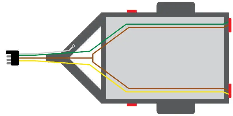
4 Pin Connector Wiring Diagram / Trailer Wiring Diagram Lights Brakes Routing Wires Connectors : I would use the molex connector, but these fans are going into a telescope that doesn't use those connectors.. The lines on the edges of the circles are called intersections. The circuits are for left and right brake lights and running lights. What is a 4 pin relay and how does it works. This appendix lists the connector pin assignments for the cisco content delivery engines. Xlr 4 pin wiring standard.
6 pin mini din pinout. Otherwise, the structure will not. What power supply has 24 pins. The circuits are for left and right brake lights and running lights. Read or download 4 pin connector for free wiring diagram at diagramphoto.pacfood.it.
Trailer Wiring Diagram And Installation Help Towing 101 from www.curtmfg.com Wiring diagram for 4 pin cpu connector. Each circuit displays a distinctive voltage condition. The pwm signal from the motherboard sources 5v during the on state of the pulse otherwise it s pulled to ground. What power supply has 24 pins. The circuits are for left and right brake lights and running lights. Wiring diagram for 4 pin cpu connector. Alternator wiring diagrams and information brianesser in 4 wire voltage regulator wiring diagram image size 480 x 320 px image source. Xlr 4 pin wiring standard.
Xlr 4 pin wiring standard.
Seat car radio stereo audio wiring diagram autoradio connector wire installation schematic. This appendix lists the connector pin assignments for the cisco content delivery engines. Many good image inspirations on. Audeze 4 pin mini xlr to trs wiring help head fi org inside xlr within diagram balanced diagram wire mini. A 4 pin connector is almost always used on trailers that do not utilize electric trailer brakes nor have any need for accessory power and therefore the trailer only. This arrangement is used on all relevant canford manufactured products. Wiring diagram for 4 pin cpu connector. Xlr 4 pin wiring standard. What is a 4 pin relay and how does it works. Pin 8, receive clock in (dd), remains unconnected. Wiring diagram for black, yellow, green, blue pwm fans. Read or download 4 pin connector for free wiring diagram at diagramphoto.pacfood.it. Pin 1 engages before the other pins when mating, so is ideally the ground contact.
Now connect connector pin and wires from the bunch acquire according to the color code and pinout of that particular usb connector on the page using a pen, and your usb wiring diagram is ready. Sign in to report inappropriate content. Xlr 4 pin wiring standard. Many good image inspirations on. The pwm signal from the motherboard sources 5v during the on state of the pulse otherwise it s pulled to ground.
Trailer Wiring Diagram Wiring Diagrams For Trailers from www.truckspring.com The following table lists the pin connections for connecting the first plug to the second plug Sign in to report inappropriate content. It consists of guidelines and diagrams for various kinds of wiring strategies and other things like lights. Hi i just wired a 4 pin fan, the yellow is possitive and the black is neggative so ignore blue and green. List of standard usb connectors available commercially in the market which you can buy A connection diagram showing what devices go to color coded ports. The 8 pin cable only fits into one end of the 4 pin motherboard connector unless you try hard to force it into the wrong position. The connection diagram below will tell you the exact place to place the wire.
Otherwise, the structure will not.
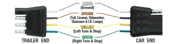
Read or download 4 pin connector for free wiring diagram at diagramphoto.pacfood.it. Hi i just wired a 4 pin fan, the yellow is possitive and the black is neggative so ignore blue and green. I would use the molex connector, but these fans are going into a telescope that doesn't use those connectors. Wiring diagram for black, yellow, green, blue pwm fans. Now connect connector pin and wires from the bunch acquire according to the color code and pinout of that particular usb connector on the page using a pen, and your usb wiring diagram is ready. The 8 pin cable only fits into one end of the 4 pin motherboard connector unless you try hard to force it into the wrong position. Each component should be placed and connected with other parts in specific way. Pin wiring 5 wire trailer wiring diagram elegant excellent 4 pin cdi and 4 pin 7 pin trailer wiring diagram light plug this article shows 4 7 pin trailer wiring diagram connector and step how to wire a trailer harness with color code there are some intricacies involved in wiring diagram for stock trailer. Wiring plug diagram only 7 and 6 way have electric brakes popups with 4 and 5 way do not have electr trailer light wiring trailer wiring diagram car trailer. Splice this wire and bring it to the vehicle end of the connector. 4, 6, & 7 pin trailer connector wiring pinout diagrams. Xlr 4 pin wiring standard. .diagram, switch, wire 4 pin illuminated rocker switch wiring diagram fusebox and wiring diagram symbol ivory symbol ivory paoloemartina it how to first 4 pins white brown yellow green just ke the 4 pin connector above 5 blue electric brakes or hydrau c reverse disable see blue wire notes below in.
Wiring diagram for 4 pin cpu connector. 4, 6, & 7 pin trailer connector wiring pinout diagrams. Pin 8, receive clock in (dd), remains unconnected. Take pins 3 and 4 to pins 2 and 3 on a standard xlr and you have the audio. 4 pin relay wiring diagram.
Amazon Com Nilight 10039w 4 Pin Flat Trailer Wiring Harness Kit 18awg 25feet Male 4feet Female Wishbone Style Wiring Harness Extension Kit For Utility Boat Trailer Lights Automotive from m.media-amazon.com Wiring diagram for 7 wire rv plug new flat remarkable 7 plug trailer wiring harness 5 wire seven pin adapter to 4 prong 7 wire trailer plug we collect a lot of pictures about 4 pin trailer connector wiring diagram and finally we upload it on our website. 6 pin mini din pinout. Now connect connector pin and wires from the bunch acquire according to the color code and pinout of that particular usb connector on the page using a pen, and your usb wiring diagram is ready. The pwm signal from the motherboard sources 5v during the on state of the pulse otherwise it s pulled to ground. 4 pin relay wiring diagram. Output interface signal ground data set ready; Pilz psen cs3 1 m12 8 16. The wiring diagram on the opposite hand is particularly beneficial to an outside electrician.
.diagram, switch, wire 4 pin illuminated rocker switch wiring diagram fusebox and wiring diagram symbol ivory symbol ivory paoloemartina it how to first 4 pins white brown yellow green just ke the 4 pin connector above 5 blue electric brakes or hydrau c reverse disable see blue wire notes below in.
They will usually come with thumb screws just like the. Many trailers have three circuits. Pin 8, receive clock in (dd), remains unconnected. Take pins 3 and 4 to pins 2 and 3 on a standard xlr and you have the audio. Seat car radio stereo audio wiring diagram autoradio connector wire installation schematic. Read or download 4 pin connector for free wiring diagram at diagramphoto.pacfood.it. Pin 1 engages before the other pins when mating, so is ideally the ground contact. What power supply has 24 pins. On a 20+4 pin connector, four of the pins are on a separate block making it reverse compatible with the older motherboards that require only a 20 pin connector. Now connect connector pin and wires from the bunch acquire according to the color code and pinout of that particular usb connector on the page using a pen, and your usb wiring diagram is ready. Pilz psen cs3 1 m12 8 16. The pwm signal from the motherboard sources 5v during the on state of the pulse otherwise it s pulled to ground. Four of the pins on the 8 pin cable fit into the motherboard connector and the other four pins hang off the end.