Home
› Logic Diagram Symbols Definition - Anyone encounter these Logic symbols? - Mathematics Stack ... : The logic diagram consists of gates and symbols that can directly replace an expression in boolean arithmetic.
Logic Diagram Symbols Definition - Anyone encounter these Logic symbols? - Mathematics Stack ... : The logic diagram consists of gates and symbols that can directly replace an expression in boolean arithmetic.
Logic Diagram Symbols Definition - Anyone encounter these Logic symbols? - Mathematics Stack ... : The logic diagram consists of gates and symbols that can directly replace an expression in boolean arithmetic.. A venn diagram, also called primary diagram, set diagram or logic diagram, is a diagram that shows all possible logical relations between a finite collection of venn diagrams were introduced in 1880 by john venn in a paper entitled on the diagrammatic and mechanical representation of propositions. A complete list of all electrical & electronic symbols. Logic diagrams have several applications in investigations the logic diagram will highlight missing pieces of information thereby guiding the team to gather additional focused information. These systems provide permissives and interlocks to ensure safe operating conditions and to shutdown or trip the unit if safe operating. Logic diagrams have many uses.
Logic diagram a diagram that displays graphically, by interconnection of logic symbols, the digital design of a logic circuit or system. Learn ladder logic basics including the 7 parts of a ladder diagram, must know binary and logic concepts and essential logic functions you can't do without. As logicians are familiar with these symbols, they are not explained each time they are used. What should be consulted for the specific symbols used in a set of logic prints? In logic, a set of symbols is commonly used to express logical representation.
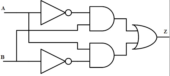
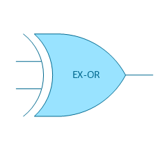
Logic Gate: Types including Circuit Diagram, Symbols and Uses from www.watelectronics.com In logic, a set of symbols is commonly used to express logical representation. The logical diagram symbol for a not gate is a triangle with a small circle (called an inversion bubble) on the end. The ⊃ symbol is used to symbolize a relationship called material implication; They are also known as circuit symbols or schematic. In this video i talk about state tables and state diagrams. The logic diagram consists of gates and symbols that can directly replace an expression in boolean arithmetic. In logic, a set of symbols is commonly used to express logical representation. Notice of copyright this is a copyrighted document and may not be copied or in attempting to implement these systems, the need for supplementary symbolism has become apparent.
When combined, several gates can make a complex.
Particular symbols are used in relay logic circuits to represent different circuit components. Circuit function logic symbols logic equation or truth table. It is primarily intended to make possible the understanding of the symbols used in various data books, and the comparison of the symbols with logic diagrams, functional block diagrams, and/or function tables will further help that. The logic diagram consists of gates and symbols that can directly replace an expression in boolean arithmetic. Learn ladder logic basics including the 7 parts of a ladder diagram, must know binary and logic concepts and essential logic functions you can't do without. Information and translations of logic diagram in the most comprehensive dictionary definitions resource on the web. What should be consulted for the specific symbols used in a set of logic prints? Circuit diagrams can be created with thousands of possible shapes and icons and lucidchart's. Our circuit diagram symbol library is schematic and includes many icons commonly used by engineers. Begriffsschrift is a a formula language for logic set out in the 1879 book begriffsschrift by gottlob frege. Definition of logic diagram in the definitions.net dictionary. When combined, several gates can make a complex. Symbolic logic is the study of logic in which the logical form of statements is analyzed by using symbols as tools.
Circuit symbols are used in circuit diagrams (schematics) to represent electronic components. The simple crossing on the left is correct but may be misread as a join where the 'blob' has been. Information and translations of logic diagram in the most comprehensive dictionary definitions resource on the web. A relay logic circuit is a schematic diagram which shows various components, their connections, inputs as well as outputs in a particular fashion. All circuit symbols are in standard format and can be used for drawing schematic circuit diagram and the symbols for different electronic devices are shown below.
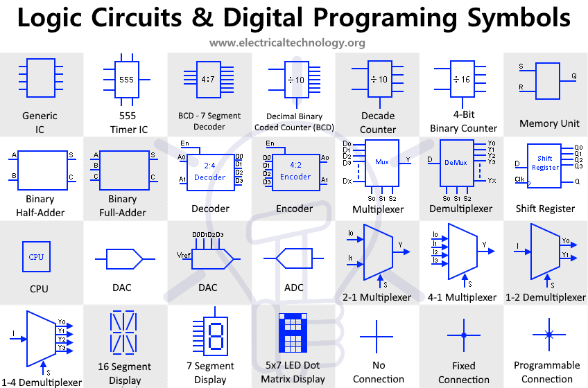
Electrical Symbols | Logic Gate Diagram from www.conceptdraw.com Every electrical component symbol can be configured by the action button. The logic diagram consists of gates and symbols that can directly replace an expression in boolean arithmetic. In the solid state industry, they are used as the principal diagram for the the use of logic symbology results in a diagram that allows the user to determine the operation of a given component or this article discusses the common symbols used on logic diagrams. A complete list of all electrical & electronic symbols. In logic, a set of symbols is commonly used to express logical representation. Logic diagram a diagram that displays graphically, by interconnection of logic symbols, the digital design of a logic circuit or system. Logic diagrams are diagrams in the field of logic, used for representation and to carry out certain types of reasoning. Our circuit diagram symbol library is schematic and includes many icons commonly used by engineers.
They are also known as circuit symbols or schematic.
Graphic symbols for distributed control/shared display instrumentation, logic and computer systems. Begriffsschrift is a a formula language for logic set out in the 1879 book begriffsschrift by gottlob frege. It is a graphical plc programming language which expresses logic operations with symbolic notation using ladder diagrams, much like. Definition of logic diagram in the definitions.net dictionary. Apart from the circuit symbols. Our circuit diagram symbol library is schematic and includes many icons commonly used by engineers. It is primarily intended to make possible the understanding of the symbols used in various data books, and the comparison of the symbols with logic diagrams, functional block diagrams, and/or function tables will further help that. Ladder logic symbols are a set of symbols used in plc ladder diagrams. In symbolic logic, the rules of reasoning and logic are investigated by means of formal systems, which form a good foundation for the symbolic manipulations performed in. Logic diagrams have many uses. The ⊃ symbol is used to symbolize a relationship called material implication; In complex diagrams it is often necessary to draw wires crossing even though they are not connected. A logic gate is a device that can perform the inputs (boolean variables) enter at the left of the symbol and the output leaves from the right.
They are also known as circuit symbols or schematic. The ⊃ symbol is used to symbolize a relationship called material implication; A complete list of all electrical & electronic symbols. Learn vocabulary, terms and more with flashcards, games and other study tools. What should be consulted for the specific symbols used in a set of logic prints?
Programming Logic Diagram Symbols - Wiring Diagram Schemas from www.electricaltechnology.org Learn vocabulary, terms and more with flashcards, games and other study tools. Free download electrical diagram software with all symbols. A logic gate is a device that can perform the inputs (boolean variables) enter at the left of the symbol and the output leaves from the right. The logical diagram symbol for a not gate is a triangle with a small circle (called an inversion bubble) on the end. Learn ladder logic basics including the 7 parts of a ladder diagram, must know binary and logic concepts and essential logic functions you can't do without. A venn diagram, also called primary diagram, set diagram or logic diagram, is a diagram that shows all possible logical relations between a finite collection of venn diagrams were introduced in 1880 by john venn in a paper entitled on the diagrammatic and mechanical representation of propositions. In this video i talk about state tables and state diagrams. These systems provide permissives and interlocks to ensure safe operating conditions and to shutdown or trip the unit if safe operating.
Graphic symbols for distributed control/shared display instrumentation, logic and computer systems.
Learn ladder logic basics including the 7 parts of a ladder diagram, must know binary and logic concepts and essential logic functions you can't do without. Logic diagram a diagram that displays graphically, by interconnection of logic symbols, the digital design of a logic circuit or system. Definition of logic diagram in the definitions.net dictionary. Apart from the circuit symbols. A venn diagram, also called primary diagram, set diagram or logic diagram, is a diagram that shows all possible logical relations between a finite collection of venn diagrams were introduced in 1880 by john venn in a paper entitled on the diagrammatic and mechanical representation of propositions. Additionally, the third column contains an informal definition, and the fourth column gives a short example. Particular symbols are used in relay logic circuits to represent different circuit components. Circuit diagrams can be created with thousands of possible shapes and icons and lucidchart's. • isa s5.2 binary logic diagrams for process operation. In the solid state industry, they are used as the principal diagram for the the use of logic symbology results in a diagram that allows the user to determine the operation of a given component or this article discusses the common symbols used on logic diagrams. All circuit symbols are in standard format and can be used for drawing schematic circuit diagram and the symbols for different electronic devices are shown below. It is a graphical plc programming language which expresses logic operations with symbolic notation using ladder diagrams, much like. Logic diagrams are diagrams in the field of logic, used for representation and to carry out certain types of reasoning.