Home
› 3 Wire Pressure Transducer Wiring Diagram : Pressure Transducer Wiring Diagram - Wiring Diagram / High level voltage or frequency output signal including 0.5 to 4.5v ratiometric current output signal, i.e.
3 Wire Pressure Transducer Wiring Diagram : Pressure Transducer Wiring Diagram - Wiring Diagram / High level voltage or frequency output signal including 0.5 to 4.5v ratiometric current output signal, i.e.
3 Wire Pressure Transducer Wiring Diagram : Pressure Transducer Wiring Diagram - Wiring Diagram / High level voltage or frequency output signal including 0.5 to 4.5v ratiometric current output signal, i.e.. So a shorted sensor will render the crank sensor all dimensions are decimal inches wiring diagrams for all transducers dimensions k1 k2 k8 pressure transducer instruction sheet. Brake fluid level sensor variable induction control servo variable induction control servo intake air temperature sensor atmospheric pressure. Refer to the installation instructions. Why do we use wiring diagrams? Pressure switches and transducers93 class 9012, 9013, 9022 and 902593.
4 wire pressure transducer wiring diagram. Following table shows wire colors related to electrical circuits. Dc 3 wire, cable type dc 3 wire, cable connector type. 30) main wiring harness/near electrical center (circuit 15), always when driver door wiring harness fitted main wiring harness/near electrical center legend of wiring diagram of manual transmission. Refer to the installation instructions.
Pressure Transducer|Transmitter 4-20mA/Voltage-Sino-Instrument from www.drurylandetheatre.com Turbocharger pressure regulation solenoid valve. Why do we use wiring diagrams? Here is a picture gallery about pressure transducer wiring diagram complete with the description of the image, please find the image you need. Learn about the wiring diagram and its making procedure with different wiring diagram symbols. Section 11 wiring diagrams subsection 01 (wiring diagrams). It shows what sort of electrical wires are interconnected which enable it to also show where fixtures and components could possibly be attached to the system. As in the wiring harness diagram is used. Connector numbers enclosed by frame are indicated with the connector symbols at the lower part of the page.
Refer to the installation instructions.
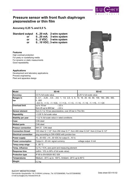
The net result of the combination of transducer and the figure 4 circuitry is a signal conditioned precision pressure sensor that is compatible thanks to dcp1 and 2 with full automation of the calibration process is very low in total power draw 1 milliampere most of. Following table shows wire colors related to electrical circuits. Industrial transmitters are available for monitoring many parameters these including pressure, temperature and flow etc. What is a wiring diagram? Do not wire more than one device per transformer. Transmitters are available with a wide variety of signal outputs. F electrical wiring diagram (system circuits). This size breaker requires a minimum of a #10 gauge wire so this wire used would be a 10/2 with ground. Section 11 wiring diagrams subsection 01 (wiring diagrams). Din 43650 a plug ip 65 : Cheap pressure transmitters, buy quality tools directly from china suppliers:ac380v/100v pressure transmitter jd194 bs4p three phase three wire four wire active power transmitter pressure transducer enjoy free shipping worldwide! 4 wire pressure transducer wiring diagram. Temperature controllers temperature/humidity transducers ssrs/power controllers counters timers panel meters tachometer/pulse (rate).
Te pressure transmitters are two wire devices (red. Pressure transducers today are more rugged and reliable than ever. Pressure units for each transducer are specified by the customer. Pressure switches and transducers93 class 9012, 9013, 9022 and 902593. Industrial transmitters are available for monitoring many parameters these including pressure, temperature and flow etc.
Pressure Transducers | Pressure Transmitters | Pressure Sensors from esi-transducer.com For engine m 111 complete axle ratio:4.29). A wiring diagram is an easy visual representation from the physical connections and physical layout of the electrical system or circuit. Connector numbers enclosed by frame are indicated with the connector symbols at the lower part of the page. Hp efi and dominator efi systems. Pressure transducers today are more rugged and reliable than ever. Section 11 wiring diagrams subsection 01 (wiring diagrams). This size breaker requires a minimum of a #10 gauge wire so this wire used would be a 10/2 with ground. Brake fluid level sensor variable induction control servo variable induction control servo intake air temperature sensor atmospheric pressure.
Terminals on the tsi controller, per figure 3.
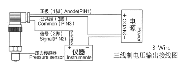
Te pressure transmitters are two wire devices (red. It shows what sort of electrical wires are interconnected which enable it to also show where fixtures and components could possibly be attached to the system. Section 11 wiring diagrams subsection 01 (wiring diagrams). Instead of wiring diagrams, wiring tables can also be used. Dc 3 wire, cable type dc 3 wire, cable connector type. Refer to the installation instructions. Do not wire more than one device per transformer. Why do we use wiring diagrams? Wire the transducer to the pressure input. Din 43650 a plug ip 65 : F electrical wiring diagram (system circuits). What is a wiring diagram? Following table shows wire colors related to electrical circuits.
Detailed images 5000 psi 3 wire pressure vacuum transducer specification 5000 psi 3 wire pressure vacuum transducer pressure 100kpa~60mpa absolute or sealed gauge pressure power supply between 12~36v output current , voltage, digital signal optional (see option page) overload 2 times. Turbocharger pressure regulation solenoid valve. Temperature controllers temperature/humidity transducers ssrs/power controllers counters timers panel meters tachometer/pulse (rate). Din 43650 a plug ip 65 : This size breaker requires a minimum of a #10 gauge wire so this wire used would be a 10/2 with ground.
3 Wire Pressure Transducer Diagram - Wiring Diagram Networks from img.yumpu.com Detailed images 5000 psi 3 wire pressure vacuum transducer specification 5000 psi 3 wire pressure vacuum transducer pressure 100kpa~60mpa absolute or sealed gauge pressure power supply between 12~36v output current , voltage, digital signal optional (see option page) overload 2 times. F electrical wiring diagram (system circuits). 30) main wiring harness/near electrical center (circuit 15), always when driver door wiring harness fitted main wiring harness/near electrical center legend of wiring diagram of manual transmission. Pressure switches and transducers93 class 9012, 9013, 9022 and 902593. Pressure transducers today are more rugged and reliable than ever. Honeywell • sensing and control 5. Wire the transducer to the pressure input. Industrial transmitters are available for monitoring many parameters these including pressure, temperature and flow etc.
Honeywell • sensing and control 5.
Din 43650 a plug ip 65 : Section 11 wiring diagrams subsection 01 (wiring diagrams). Automatic transmission idling speed solenoid unit. In this video, we show you how to wire a pressure transducer two ways: Here is a picture gallery about pressure transducer wiring diagram complete with the description of the image, please find the image you need. F electrical wiring diagram (system circuits). Wiring diagram for pressure transducer. Terminals on the tsi controller, per figure 3. Following table shows wire colors related to electrical circuits. Control output diagram & load operation. The cable is terminated at the pressure transducer and at the tsi controller or monitor. Honeywell • sensing and control 5. Temperature controllers temperature/humidity transducers ssrs/power controllers counters timers panel meters tachometer/pulse (rate).