Home
› Electric Circuit Diagram Symbols : 10 Common Electrical Symbols Found On Electrical Schematic Diagrams Electronic Products / Learn vocabulary, terms and more with flashcards, games and other study tools.
Electric Circuit Diagram Symbols : 10 Common Electrical Symbols Found On Electrical Schematic Diagrams Electronic Products / Learn vocabulary, terms and more with flashcards, games and other study tools.
Electric Circuit Diagram Symbols : 10 Common Electrical Symbols Found On Electrical Schematic Diagrams Electronic Products / Learn vocabulary, terms and more with flashcards, games and other study tools.. Ciircuits, diagrams & symbols includes: Below is an overview of the most used symbols in circuit diagrams. It can be used for a zero potential reference point from where current is measured. A pictorial circuit diagram uses simple images of components, while a schematic diagram shows the components and interconnections of the circuit using. A drawing of an electrical or electronic circuit is known as a circuit diagram, but can circuit or schematic diagrams consist of symbols representing physical components and lines representing wires or electrical conductors.
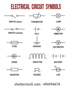
Electronic component symbols are used to denote the components in circuit diagrams. Lamps and other components in these different paths are said to be in parallel. The diagram shows some common circuit symbols. Quickly create printable electrical circuit symbol flash cards. The symbols are used to represent both active and passive components.
Circuit Diagram Symbols A Block Diagram Of A Computer System Bege Wiring Diagram from i.pinimg.com All circuit symbols are in standard format and can be used for drawing schematic circuit diagram and layout. Start studying electric circuit symbols. Circuit symbols overview resistors capacitors inductors, coils, chokes & transformers diodes bipolar transistors field today, circuit symbols and their usage has been pretty much standardised. A final means of describing an electric circuit is by use of conventional circuit symbols to provide a schematic diagram of the circuit and its components. We use circuit symbols to draw diagrams of electrical circuits, with straight lines to show the wires. Lamps and other components in these different paths are said to be in parallel. An electrical circuit is a simplified representation of an electric circuit element. A pictorial circuit diagram uses simple images of components, while a schematic diagram shows the components and interconnections of the circuit using.
Our circuit diagram symbol library is schematic and includes many icons commonly used by engineers.
Learn vocabulary, terms and more with flashcards, games and other study tools. Circuit symbols are used in circuit diagrams (schematics) to represent electronic components. Standard electrical iec symbols also known as iec 60617 (british standard bs 3939) used to represent various devices including pilot lights, relays, timers and switches for usage in electrical schematic diagrams. Switch symbols and relay symbols. In complex diagrams it is often necessary to draw wires crossing even though they are not connected. It can be used for a zero potential reference point from where current is measured. Electronic component symbols are used to denote the components in circuit diagrams. The simple crossing on the left is correct but may be misread as a join where the 'blob' has been. Circuit symbols overview resistors capacitors inductors, coils, chokes & transformers diodes bipolar transistors field today, circuit symbols and their usage has been pretty much standardised. Circuit symbols and circuit diagrams. The diagram shows some common circuit symbols. The schematic diagram of a simple electric circuit is shown below. An electrical circuit is a simplified representation of an electric circuit element.
Common circuit symbols exist as a near universal electric circuit symbols flashcards. Later when you come across symbols you don't know, you can come back here to identify what it is. Below is a table of the most commonly used electrical symbols used in circuit diagrams. See more ideas about electrical circuit symbols, electrical symbols, electrical diagram. These electrical circuits are demonstrated by lines to represent wires and symbols to represent electrical & electronic constituents, as it aids in better apprehending the connection between distinct components.
Wiring Diagram Symbol Reference Pietrodavico It Diode Gossip Diode Gossip Pietrodavico It from i.pinimg.com There are standard symbols for each of the components which represent that particular component. Ciircuits, diagrams & symbols includes: Electricians depend upon an electric circuit diagram for initiating any building wiring. An electrical circuit is a simplified representation of an electric circuit element. It acts as short circuit with ac and open circuit with dc. Capacitor is used to store electric charge. Circuit symbols and circuit diagrams. The actual layout of the components is usually quite different from the circuit diagram.
These diagrams are drawn using standard industrial symbols.
The wattmeter is an instrument for measuring the electric power in watts of any given circuit. Below is a table of the most commonly used electrical symbols used in circuit diagrams. Learn to read electrical and electronic circuit diagrams or schematics. Switches are electronic devices designed to interrupt or divert the flow of electric current or signals in a circuit. Our circuit diagram symbol library is schematic and includes many icons commonly used by engineers. Electricians depend upon an electric circuit diagram for initiating any building wiring. There are standard symbols for each of the components which represent that particular component. Capacitor is used to store electric charge. It is difficult to assume the practical use of. Circuit symbols are used in circuit diagrams (schematics) to represent electronic components. We use circuit symbols to draw diagrams of electrical circuits, with straight lines to show the wires. Apart from the circuit symbols, each device is also designated a short name. Circuit symbols are used in circuit diagrams which show how a circuit is connected together.
Complete circuit symbols of electronic components. Electrical circuits library contains 49 electrical element symbols of electrical and electronic devices, including ignitors, starters, transmitters, circuit protectors, transducers, radio and audio equipment. There are standard symbols for each of the components which represent that particular component. Circuit symbols are used in circuit diagrams which show how a circuit is connected together. Ciircuits, diagrams & symbols includes:
Circuit Diagram Symbols Hd Stock Images Shutterstock from image.shutterstock.com As nowadays there is no single standard. Basic electronic components symbols | eectronic circuit simulation. Electrical symbols virtually represent the components of electrical and electronic circuits. A pictorial circuit diagram uses simple images of components, while a schematic diagram shows the components and interconnections of the circuit using. Learn vocabulary, terms and more with flashcards, games and other study tools. All circuit symbols are in standard format and can be used for drawing schematic circuit diagram and layout. Create electrical circuit diagrams and schematics with electrical symbols provided by smartdraw software. It is difficult to assume the practical use of.
A drawing of an electrical or electronic circuit is known as a circuit diagram, but can circuit or schematic diagrams consist of symbols representing physical components and lines representing wires or electrical conductors.
The wattmeter is an instrument for measuring the electric power in watts of any given circuit. Click on each link given below to view the symbols. Common circuit symbols exist as a near universal electric circuit symbols flashcards. Ladder logic diagram symbols । how to interpret plc symbols. Lamps and other components in these different paths are said to be in parallel. Our circuit diagram symbol library is schematic and includes many icons commonly used by engineers. The actual layout of the components is usually quite different from the circuit diagram. Circuit symbols overview resistors capacitors inductors, coils, chokes & transformers diodes bipolar transistors field today, circuit symbols and their usage has been pretty much standardised. This enables anyone to read a circuit diagram and know what it. July 21, 2020february 24, 2012 by electrical4u. These electrical circuits are demonstrated by lines to represent wires and symbols to represent electrical & electronic constituents, as it aids in better apprehending the connection between distinct components. In circuit diagrams, various circuit elements are represented by standard electric symbols. See more ideas about electrical circuit symbols, electrical symbols, electrical diagram.