Home
› Led Vu Meter Circuit Diagram With Pcb Layout : LED VU Meter Circuit Diagram using LM3914 and LM358 : How the 8 led vu meter using lm324 ic work?
Led Vu Meter Circuit Diagram With Pcb Layout : LED VU Meter Circuit Diagram using LM3914 and LM358 : How the 8 led vu meter using lm324 ic work?
Led Vu Meter Circuit Diagram With Pcb Layout : LED VU Meter Circuit Diagram using LM3914 and LM358 : How the 8 led vu meter using lm324 ic work?. ▻ pcb circuit diagram download: Audio jack is directly connected at analog pin a5 of arduino. Column lights led projects circuit diagram shop layout. Draw your circuits and simulate them online for free using easyeda. It is the collection of a few active and passive components.
Circuit diagram and working explanation: It is the collection of a few active and passive components. Vu meter uses just one ic and a very few number of external components. Draw your circuits and simulate them online for free using easyeda. Building a smart master/slave switch schematic circuit diagram.
Pin su ELECTRONIC n ELECTRICITY from i.pinimg.com The 9 volt supply, resistor and led are laid out as they would be if the transistor circuit has been converted to a pcb layout. We have listed many free and paid pcb drawing software's and simulation tools before. The circuit of a simple led vu meter explained here uses the outstanding chip lm3915 from the circuit diagram shows a very simple configuration employing two of the above ics in the on a side note do you have suggestions for hobbyist level circuit design software with pcb layout capability? Doorbell with security feature schematic circuit diagram. How the 8 led vu meter using lm324 ic work? The circuit diagram on the left clearly shows a simple led circuit. Vu meter uses just one ic and a very few number of external components. Hallo sahabat dan sobat ketemu lagi di blogkamarku.com yang.
Hallo sahabat dan sobat ketemu lagi di blogkamarku.com yang.
1x lm3915 1x 100k resistor 1x 2,2k. The output signal of an audio amplifier (which is connected to. To design circuit and pcb for this vu meter shield, we chose easyeda which is a free online tool and one stop solution for developing your electronics we have made the circuit and pcb design of this vu meter shield public, so you can just follow the link to access the circuit diagram and pcb layouts. Led circuit as a pcb layout. Led current drive is regulated and programmable, eliminating the need for current limiting resistors. There is no doubt that schematic creation and pcb layout are fundamental aspects of electrical engineering, and it makes sense that resources such as technical articles, app notes, and textbooks tend to focus on guide to ordering and assembling printed circuit boards. Sgl8022w touch led pwm module schematic circuit diagram. Your browser does not support the video tag. We have listed many free and paid pcb drawing software's and simulation tools before. Doorbell with security feature schematic circuit diagram. It is the collection of a few active and passive components. The most common and used type of printed circuit boards is the rigid type, but the flex one is another type that you may think of using it after getting yourself familiar with, especially that it is now more available than before as more. Draw your circuits and simulate them online for free using easyeda.
Sgl8022w touch led pwm module schematic circuit diagram. Led volume meter is an equalizer in the music systems. Build your own quote board with adafruit io and an led matrix display. Lượt xem 7 ntháng trước. Led current drive is regulated and programmable, eliminating the need for current limiting resistors.
Pin em Vu meter from i.pinimg.com It is the collection of a few active and passive components. High performance vu meter circuit projects using lm3914/lm3915 that widely popular can display with 20 leds on stereo for all audio system. Led current drive is regulated and programmable, eliminating the need for current limiting resistors. I am back and i am still thinking of building this great project. How to make led vu meter circuit an6884 simple. The circuit diagram on the left clearly shows a simple led circuit. This 8 led vu meter circuit can be used to display the variation of an audio signal in a group of 8 leds, behaving like the 8 op amps are used as voltage comparators. At first mic picks up the sound and converts it into voltages levels linear to the intensity of sound.
I am back and i am still thinking of building this great project.
The 9 volt supply, resistor and led are laid out as they would be if the transistor circuit has been converted to a pcb layout. D.i.y led vu meter pcbway 3rd pcb design contest pcbway pcb. Audio jack is directly connected at analog pin a5 of arduino. High performance vu meter circuit projects using lm3914/lm3915 that widely popular can display with 20 leds on stereo for all audio system. Circuit diagram and working explanation: All free electronics projects and free download. The circuit diagram of the vu meter is show in below figure, working of vu meter circuit is simple; Voltage regulator as audio amplifier schematic circuit diagram. Led circuit as a pcb layout. The performance of your circuit will depend greatly on how it's laid out on the pcb, so i'll give you lots of identify what each part of your circuit does, and divide the circuit into sections according to the location of components like power connections, potentiometers, leds, and audio jacks in your. Led current drive is regulated and programmable, eliminating the need for current limiting resistors. It is the collection of a few active and passive components. 1x lm3915 1x 100k resistor 1x 2,2k.
Lượt xem 7 ntháng trước. The performance of your circuit will depend greatly on how it's laid out on the pcb, so i'll give you lots of identify what each part of your circuit does, and divide the circuit into sections according to the location of components like power connections, potentiometers, leds, and audio jacks in your. We have listed many free and paid pcb drawing software's and simulation tools before. Building a smart master/slave switch schematic circuit diagram. Jlcpcb prototype for $2(any color):
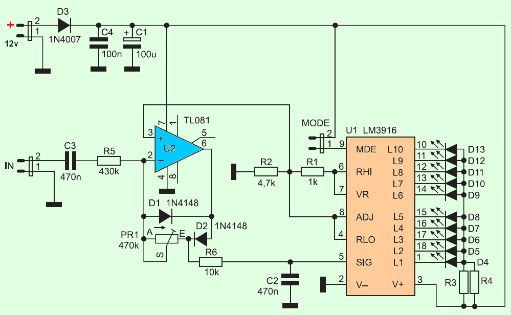
20 dB Vu meter Circuit LM3916 - Electronics Projects Circuits from 320volt.com 120 led stereo vu meter circuit 120 led ka2281 vu metre devresi sprint layout pcb, gerber download circuit diagram download: There is no doubt that schematic creation and pcb layout are fundamental aspects of electrical engineering, and it makes sense that resources such as technical articles, app notes, and textbooks tend to focus on guide to ordering and assembling printed circuit boards. Subwoofer booster circuit is used to enhancing or boosting or increase the subwoofer amplifier, but it also can improve the quality of the bass sound on an amplifier or high power amplifier. The 9 volt supply, resistor and led are laid out as they would be if the transistor circuit has been converted to a pcb layout. Column lights led projects circuit diagram shop layout. This 8 led vu meter circuit can be used to display the variation of an audio signal in a group of 8 leds, behaving like the 8 op amps are used as voltage comparators. The most common and used type of printed circuit boards is the rigid type, but the flex one is another type that you may think of using it after getting yourself familiar with, especially that it is now more available than before as more. How to make led vu meter circuit an6884 simple.
I am back and i am still thinking of building this great project.
String led circuit diagram constant current power supply. High performance vu meter circuit projects using lm3914/lm3915 that widely popular can display with 20 leds on stereo for all audio system. How the 8 led vu meter using lm324 ic work? Led volume meter is an equalizer in the music systems. 6 led vu meter using one transistor this simple vu meter allows us to visualize the level of an how to make a simple vu meter with 80 leds ic lm3915. The most common and used type of printed circuit boards is the rigid type, but the flex one is another type that you may think of using it after getting yourself familiar with, especially that it is now more available than before as more. Audio jack is directly connected at analog pin a5 of arduino. At first mic picks up the sound and converts it into voltages levels linear to the intensity of sound. Subwoofer booster circuit/bass enhancer circuit based on the ic 4558 and tl074 or commonly known as ic. Led current drive is regulated and programmable, eliminating the need for current limiting resistors. Column lights led projects circuit diagram shop layout. Draw your circuits and simulate them online for free using easyeda. This is not an eagle file.