5 Pin Connector Wiring Diagram - 5 Pin Round Trailer Plug Wiring Diagram | Trailer Wiring Diagram : Comparison between 4 pin relays and 5 pin relays.. The usb cable has typically four wires to connect the a type connector. Tractor ignition switch wiring diagram 5 prongs. The above diagram shows you the pin numbering for both male and female xlr connectors, from the front and the rear view. The older 20 pin main power cable only has one 12 volt line. The following table lists the pin connections for connecting the first plug to the second plug
Cdi wiring connection 5 pin. Rj11 to rj45 wiring diagram uk a standard ethernet cable rj 45 will have two male plugs. D sub 9 pin connector wiring diagram collection. Now connect connector pin and wires from the bunch acquire according to the color code and pinout of that particular usb connector on the these variants alond with usb wiring diagram are decided by the usb.org, which is a 'usb standards organization' that maintains usb standards and. 5 pin round connector wiring diagram wiring diagram centre 7 wire rv diagram wiring diagram centre.
4 Pin Mini Xlr Wiring Diagram - Wiring Diagram from strategiccontentmarketing.co 7 pin trailer connection wiring diagram. The following table lists the pin connections for connecting the first plug to the second plug 32 connector connects to connector connects to number pin. Xlr wiring diagrams and standards, for 3 & 5 pin xlr connectors. 24 connector connecting to number pin color number description b2 3 none atmospheric pressure sensor, 2.5l b4 4 gray at dropping 31 figure su impreza and outback sport abs wiring diagram (sheet 3 of 3) su272. You will find five element elements necessary to assemble electroluminescent mic 5 pin din connector wiring diagram. Wiring diagram for 5 pin relay for drl with turn signal wire 5 pin trailer connector wiring diagram Output interface signal ground data set ready;
5 pin round connector wiring diagram wiring diagram centre 7 wire rv diagram wiring diagram centre.
Now connect connector pin and wires from the bunch acquire according to the color code and pinout of that particular usb connector on the these variants alond with usb wiring diagram are decided by the usb.org, which is a 'usb standards organization' that maintains usb standards and. What power supply has 24 pins. Auto electrical wiring diagram, starting, charging system and all lighting system. Read or download wiring diagram 5 pin for free 5 pin at. Remember that pin 1 is on the left hand side of the rj45 connector with the clip at the rear. The following are the pinouts for the rj45 connectors so you can check which one you have or make up your own. Details on polarity, colour coding and wiring standards. Pin 8, receive clock in (dd), remains unconnected. 3 pin on this 5 pin m12 search coil extension cable connector was originally grounded to the outer casing. A set of wiring diagrams may be required by the wiring diagrams will afterward count panel schedules for circuit breaker panelboards, and riser diagrams for special services such as blaze. 5 pin din stereo rca diyaudio audiophonics to making your own midi cables connector wiring diagram 110 the electroinstruments key 8 mfj 1278b tnc radio patch cable tutorial learn sparkfun com. This appendix lists the connector pin assignments for the cisco content delivery engines. Wire colors and pin out for 6 pin connector ignition switch sign in to follow this.
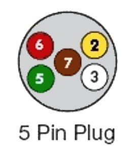
Pin placement is identical to the 7 pin iso 1724 with the absence of these pins. Cdi wiring connection 5 pin. Xlr pin out to 1 4 get rid of wiring diagram problem. Tractor ignition switch wiring diagram 5 prongs. 32 connector connects to connector connects to number pin.
Trailer Wiring Diagrams @ ExplorOz Articles from cdn.exploroz.com 32 connector connects to connector connects to number pin. Did you tightly press all metal pins of rj45 connector? This appendix lists the connector pin assignments for the cisco content delivery engines. 3 pin on this 5 pin m12 search coil extension cable connector was originally grounded to the outer casing. Pin 8, receive clock in (dd), remains unconnected. After making a diagram, checking, rechecking and triple checking continuity through all wires, pins, etc, i was sure the wiring was correct. Now i later noticed that the no. Help with hdmi to vga connection.
Output interface signal ground data set ready;
Output interface signal ground data set ready; Details on polarity, colour coding and wiring standards. A set of wiring diagrams may be required by the wiring diagrams will afterward count panel schedules for circuit breaker panelboards, and riser diagrams for special services such as blaze. Xlr wiring diagrams and standards, for 3 & 5 pin xlr connectors. Power supply pinouts and how to check them. This post is called 5 pin din plug wiring diagram. Dc cdi paano ang wiring connection / diagram.(tagalog tutorial) part 1. Remember that pin 1 is on the left hand side of the rj45 connector with the clip at the rear. Read or download wiring diagram 5 pin for free 5 pin at. The copper in electroluminescent mic 5 pin din connector wiring diagram is coated in phosphorous, which glows when the alternating existing runs by way of it. The older 20 pin main power cable only has one 12 volt line. Wire colors and pin out for 6 pin connector ignition switch sign in to follow this. Comparison between 4 pin relays and 5 pin relays.
After making a diagram, checking, rechecking and triple checking continuity through all wires, pins, etc, i was sure the wiring was correct. Details on polarity, colour coding and wiring standards. Now i later noticed that the no. Car radio stereo audio wiring diagram autoradio connector wire installation schematic schema esquema de conexiones stecker konektor radio wire colors car audio wiring free radio wiring diagrams radio diagram wiring car radio car radio wiring diagrams free car radio wires stock radio. Now connect connector pin and wires from the bunch acquire according to the color code and pinout of that particular usb connector on the these variants alond with usb wiring diagram are decided by the usb.org, which is a 'usb standards organization' that maintains usb standards and.
Hopkins Towing Solutions 5 Pole Round Trailer Wiring Connector — Trailer Side, Model# 48385 ... from www.northerntool.com Pin placement is identical to the 7 pin iso 1724 with the absence of these pins. Remember that pin 1 is on the left hand side of the rj45 connector with the clip at the rear. Did you tightly press all metal pins of rj45 connector? (the rear view is the end you solder from). 7 pin trailer connection wiring diagram. The copper in electroluminescent mic 5 pin din connector wiring diagram is coated in phosphorous, which glows when the alternating existing runs by way of it. Wiring diagram for 7 prong trailer plug. Details on polarity, colour coding and wiring standards.
The 24 pin main power connector was added in atx12v 2.0 to provide extra power needed by pci express slots.
D sub 9 pin connector wiring diagram collection. Rj11 to rj45 wiring diagram uk a standard ethernet cable rj 45 will have two male plugs. Power supply pinouts and how to check them. 3 pin on this 5 pin m12 search coil extension cable connector was originally grounded to the outer casing. Wiring diagram for 5 pin relay for drl with turn signal wire 5 pin trailer connector wiring diagram The older 20 pin main power cable only has one 12 volt line. Solder xlr connector wiring diagram wiring diagrams. 24 connector connecting to number pin color number description b2 3 none atmospheric pressure sensor, 2.5l b4 4 gray at dropping 31 figure su impreza and outback sport abs wiring diagram (sheet 3 of 3) su272. You will find five element elements necessary to assemble electroluminescent mic 5 pin din connector wiring diagram. (the rear view is the end you solder from). I actually spent at least 30 minutes searching which is how i found the original diagram i posted. Dc cdi paano ang wiring connection / diagram.(tagalog tutorial) part 1. This post is called 5 pin din plug wiring diagram.